Table of Contents
Introduction
A long while back I scratch built a 1:144th scale T-16 Skyhopper. I chose 1:144 scale to match the majority of the Bandai Vehicle Model Star Wars kits, like their X-wing, etc... and their other 1:144 scale SW kits, which are great for someone with limited display space. It was my first ever total scratch build, and while I was reasonably happy with it, it wasn't even close to what you'd call "accurate". Fast forward to a year later when I got a Cricut Maker electronic cutting machine, and the all flat-sided T-16 was an obvious first project to improve on my crude first attempt.
With electronic cutting machines being cable of cutting incredibly precisely at a resolution of down to 0.5mm, it quickly became apparent that I could engineer a kit of pieces to fit together with guaranteed (or nearly guaranteed) alignment.
The evolution of the project can be tracked in this photoset on flickr -- 1:144 T-16 Skyhopper #2 and a build thread on britmodeller.com.


Notes on the Kit
Before beginning, please keep in mind that THIS IS NOT A PROJECT FOR BEGINNERS. I've engineered everything to fit together as easily as possible, but the fact remains that it is comprised of very small, very fragile parts, that require careful cutting and sanding and drilling and can break very easily, to produce a model that's only a couple of inches tall.
That said, it is incredibly satisfying to have a tiny T-16 Skyhopper at the end.
I initially intended to produce ready to build kits, with pre-cut styrene pieces and resin casts of all the 3D printed parts. However, due to life getting in the way, that just wasn't feasible. So, I've made the files available, and the 3D printed parts can be obtained from Shapeways if you don't have access to a 3D printer. If you do have access to a 3D printer, I HIGHLY recommend using an SLA resin printer, such as an Anycubic Photon or a Form 2.
Reference Links
This project couldn't exist without the incredible work many others have done to research and replicate the original T-16 skyhopper model. All I really did was adapt and miniaturize it based on the incredible reference material others have amassed, including the studio scale replicas.
- Cantwell T16 Skyhopper research thread on the Replica Prop Forum.
- Jason Eaton's studio scale replica
- Nicholas Sagan's studio scale T-16 pair. He's also built a 1:72 scale version based off of this 1:144 design.
Materials
0.020" sheet polystyrene
You will need a sheet of 0.020" (0.5mm) styrene. I recommend Evergreen or Plastruct. Do NOT use any thickness other than .020", or the parts will not fit together. All the interlocking slots used to guarantee positioning and alignment are made for 0.020" material.
.047" steel music wire (1.2mm, K&S 502)
This is used for the support rod.
.032" steel music wire (0.8mm, K&S 501)
For the main gun barrel shaft.
1/16" aluminum tubing (1.6mm, K&S 8100)
For the main gun barrel.
3/32" round styrene tubing (Plastruct 90603)
For attaching the main gun to the undercarriage. This tubing slips over the .047" steel wire use for the main mount rod.
3/64" (1.2mm) styrene angle (Plastruct 90501)
Two 3/4" lengths of this for the lower wing "skis".
3D printed greeblies
Get them on Shapeways - 1:144 T-16 Greeblies by monsterpartywars, or use the link below to down the STL and print them yourself.
Downloads
The files below are original works licensed under the terms of the Creative Commons Attribution-NonCommercial-ShareAlike license. You are free to copy and redistribute the files with proper attribution, and you may modify and use them to build derivative works provided those works are distributed under the same terms. You MAY NOT use these files for commercial purposes. You MAY NOT sell them or any works derived from them.
By downloading these files you are agreeing to the terms of the license.
Instructions
Cutting the Styrene Parts

Importing to Cricut Design Space
Cricut Design Space is terrible about preserving the dimensions of SVG files correctly on import. After importing the SVG and placing it in a project you'll need to re-scale it. The proper dimensions are 4.59" x 2.46", or 116.5mm x 62.5mm.
Cricut - please fix your software.
The 2D pattern is intended for use in an electronic cutting machine, such as the Cricut Maker or Cameo Silhouette. I have a Cricut Maker, so the guidelines here are for that machine. If you cut one of these on a Silhouette, please let me know what settings you use and I can post them here.
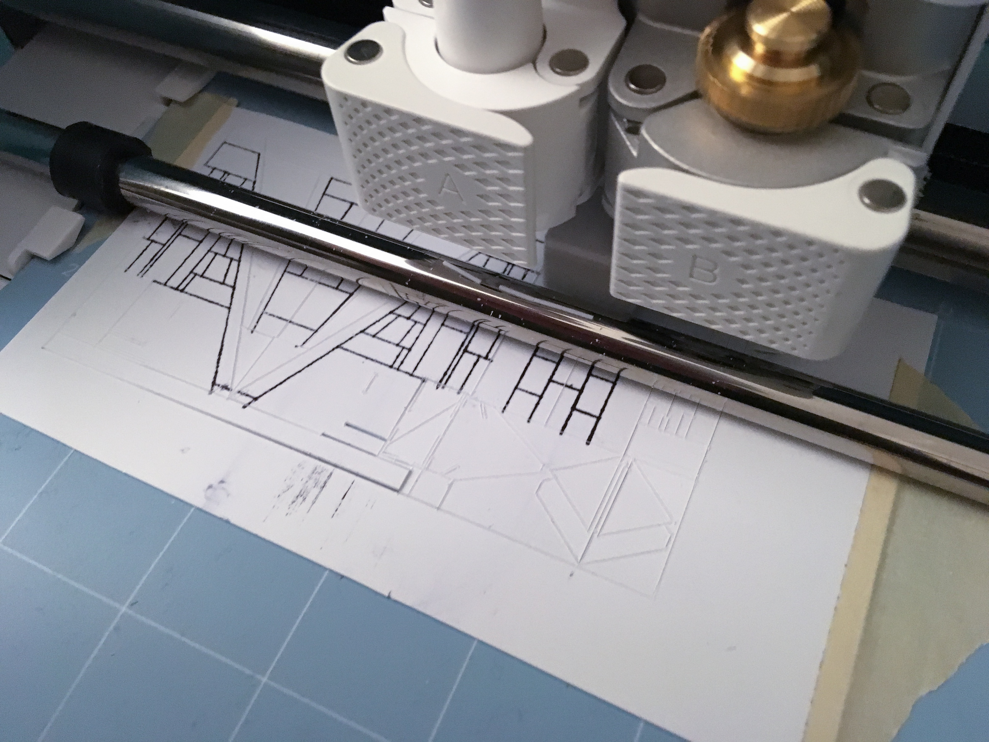
Cutting on a Cricut Maker
Settings for the Cricut Maker:
- Black lines - cut with the Knife Blade
- Red lines - draw with a marker or pencil
Knife blade settings - 1/16" or 3/32" balsa wood setting works well.
There is unfortunately currently no tool that can scribe those lines well in the second tool holder without warping the material, so I set up my machine with a pen in the second tool holder, and then use a straight edge and a Tamiya Scriber to scribe the panel lines manually after the parts are cut.
Assembling the Styrene Parts
At every step of assembly here, the flat styrene parts should be glued together with a thin styrene cement, like Tamiya Extra Thin Cement. If you have styrene filler, use that to reinforce the joints.
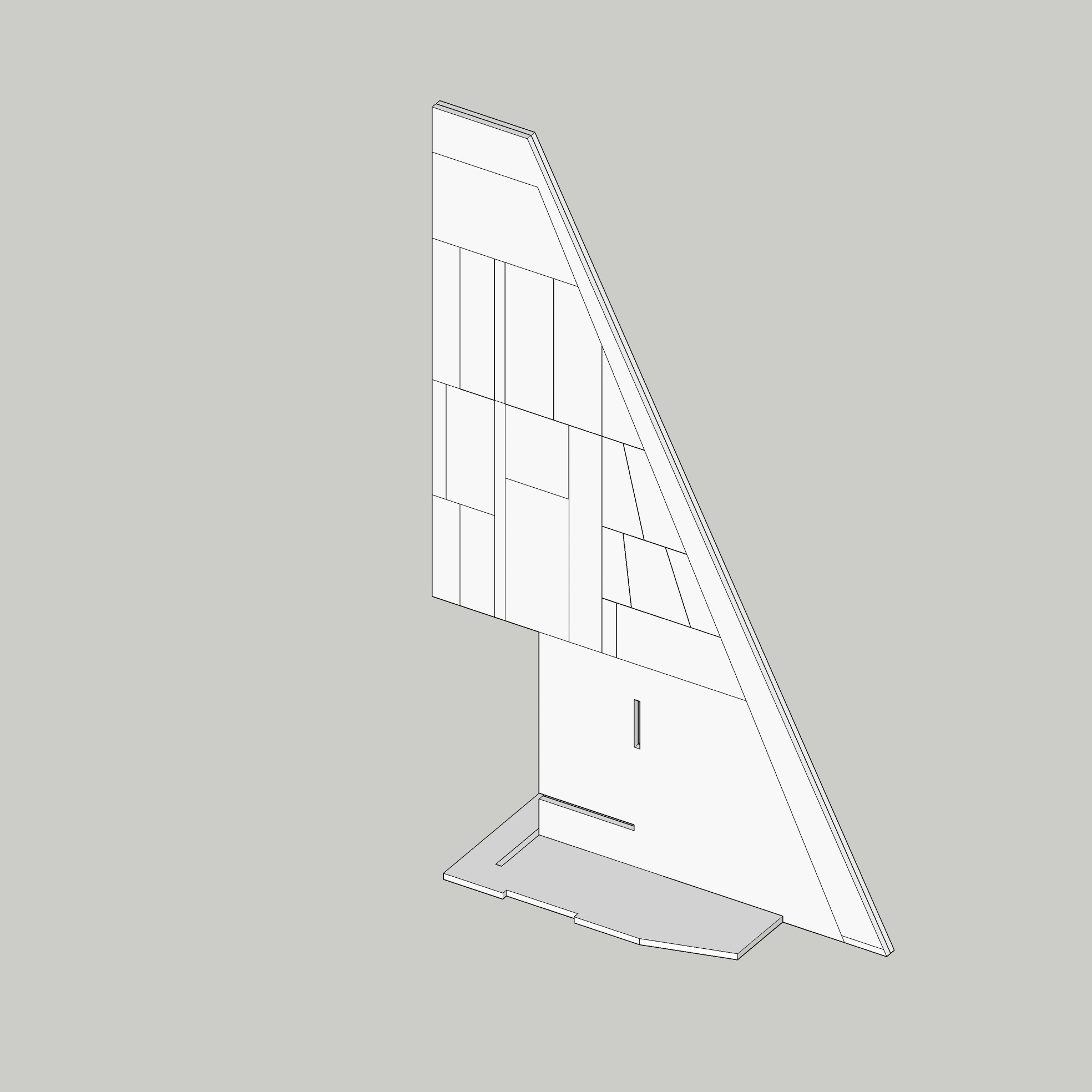
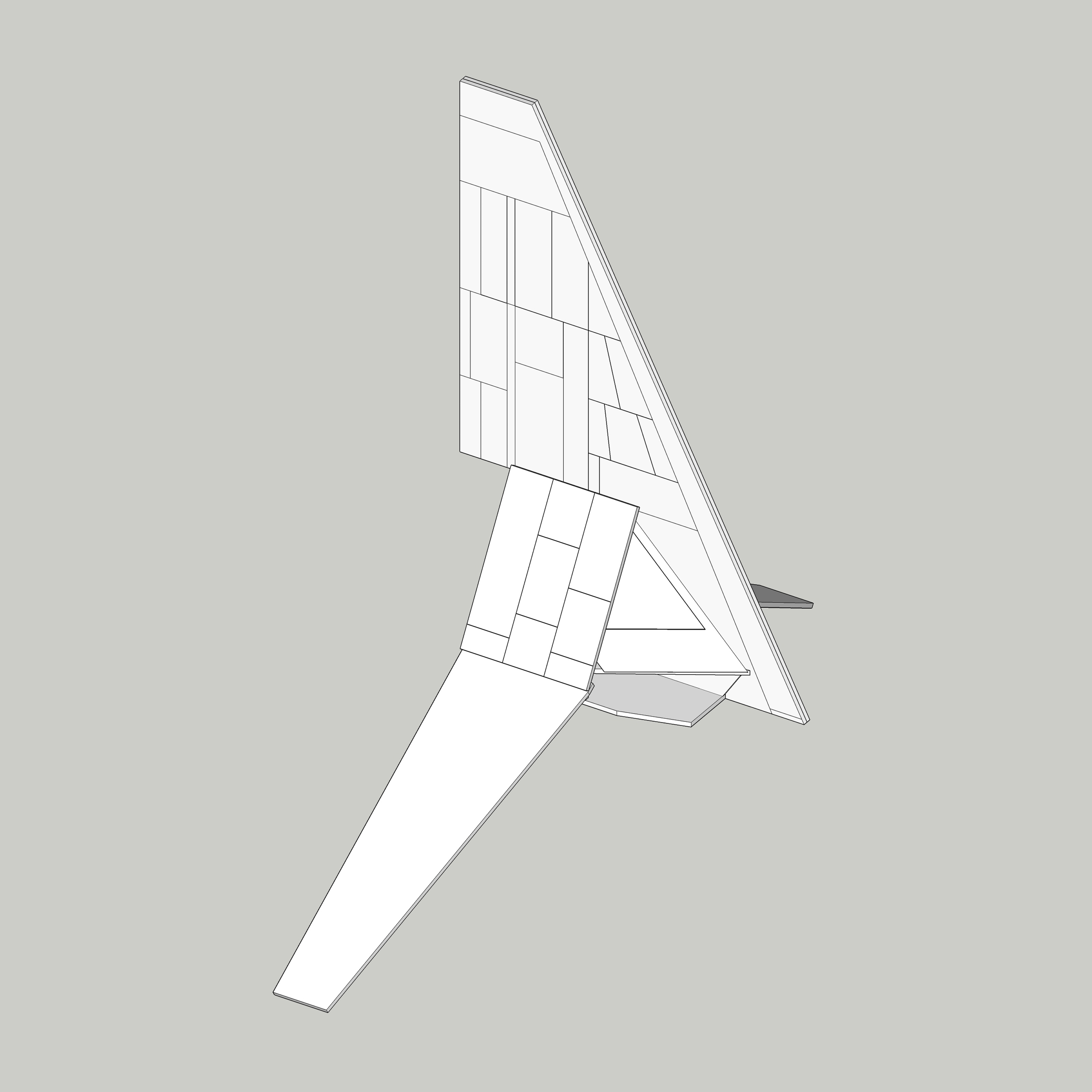
01 - Main Wing


Start by cementing both halves of the main wing together, taking care to ensure the edges are aligned evenly.
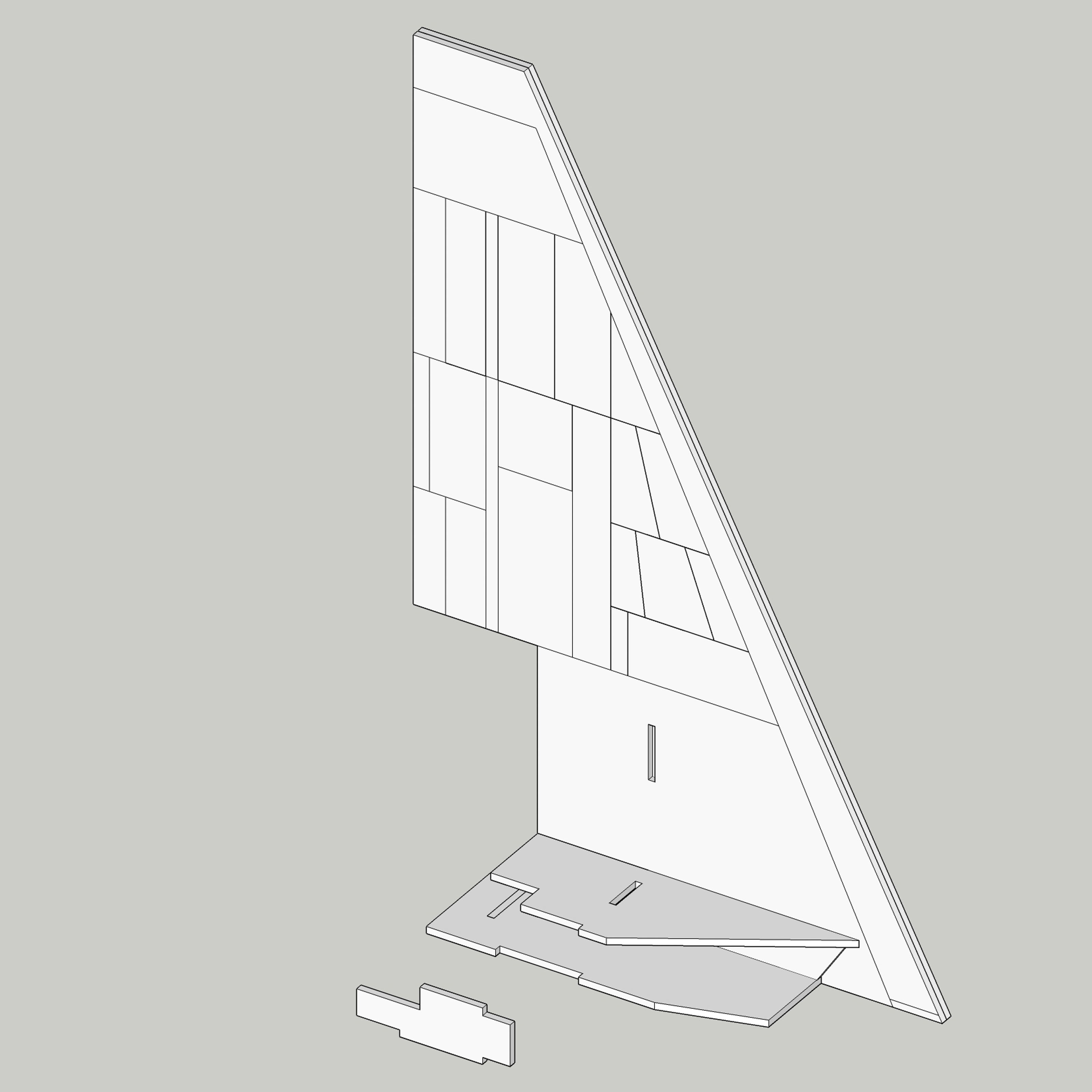
02 - Chassis Base

Next up, add the bottom of the chassis. It has a slot in the front which matches the long tab on the base of the main wing for proper alignment.
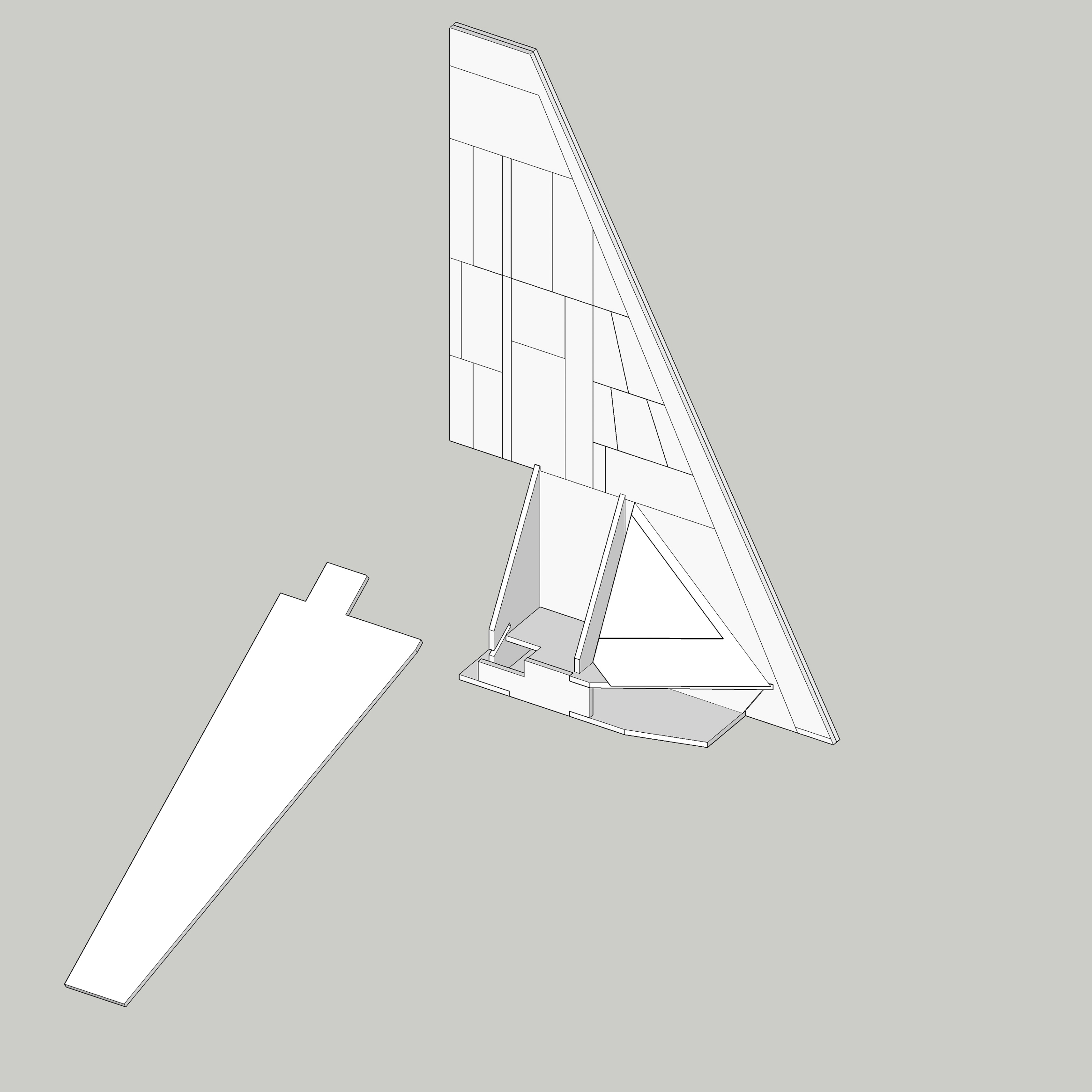
03 - Chassis Internal Support


A couple of pieces attach flush to the main wing, which will provide a spacer and mounting point for the cockpit floor. Repeat for both sides of the main wing.
04 - Cabin Floor


The cabin floor slides into place from the rear. Take care with the long slot, work it in slowly, so as not to damage the piece. Make sure it's aligned flush against the supports from the previous step.
05 - Chassis Sidewall

Next are two very small side pieces, which simply link the upper and lower chassis pieces, completing the chassis box. Repeat for both sides.
06 - Cabin Rear Wall


The rear wall of the cabin has a very small notch in the nose to keep the top aligned on the main wing, and a tab that fits into a slot on the chassis bottom.
07 - Cabin Front Wall


Glue the cabin front wall in place - if the tabs dont fit into the slots, they can be removed; they're not necessary for strength, they're there for alignment. Glued along both edges, the joint will be strong. Ensure that the piece is vertical. Repeat for both sides.
08 - Cockpit Face


Glue the cockpit window pane onto the back of the cockpit window frame, ensuring they're flush. Repeat for both sides, ensuring they're mirror images for the right and left sides.


Glue the window assembly onto the main frame, aligning with the lower edge of the chassis, all the way to the front. Repeat for both sides.
09 - Lower Wings

The lower wings slide into a slot in the rear cabin wall which holds them at the correct angle. The back of the tab in the wing should be flush with the back of the rear cabin wall - later the main engine will go over it.
Repeat for both sides.
10 - Lower Wing Bracer


The lower wing bracer is slightly tricky, as it must be centered, attached to the underside of the main chassis, and bend onto the underside of the lower wings. Go slowly and carefully. If it snaps at the bend point it won't be noticeable once the greeblies are installed.
It is helpful to clamp the model upside down by the main wing to work on the underside.
11 - Cabin Outer Wall

Finally, the cabin outer walls are placed on top of the rear and front walls. Align with the lower wing. Repeat for both sides. And that completes the styrene frame!
Adding the 3D Printed Greeblies

If at times it feels like the greeblies are in more parts than necessary, it's because they were designed to be molded and cast in a one piece silicone mold, so they've been pieced out and designed to minimize undercuts.
12 - Middle Greeble


Remove the middle greeblies from the sprue and sand the sides smoothe, then slide into the center chassis. Dry fit them before gluing - it may require additional sanding to get them to fit perfectly. Go slowly and don't overdo it.
Repeat for both sides.
13 - Main Engine


The main engine piece slides straight into the rear cavity formed by the rear cabin wall and the outer cabin walls. It will probably need some sanding along the edges to get a perfect fit - as with the middle greeblies, go slow, and dry fit it before gluing in place.
14 - Sensor Vane and Wing Buttons


The large sensor vane on the main wing is comprised of 4 individual parts, which all need to be brought together sitting on the main wing. There are two sides of the main cylinder, and front and rear end caps.


The main wing buttons are one of the trickiest pieces, as they're very small, and must be trimmed down extensively from the 3D printed sprue. Take your time, sand them against a piece of sand paper on a flat surface, and don't lose them.
15 - Underside

The underside is pretty straightforward - make sure the rear piece is facing the correct way (the flat part faces forward, to mate with the undercarriage).
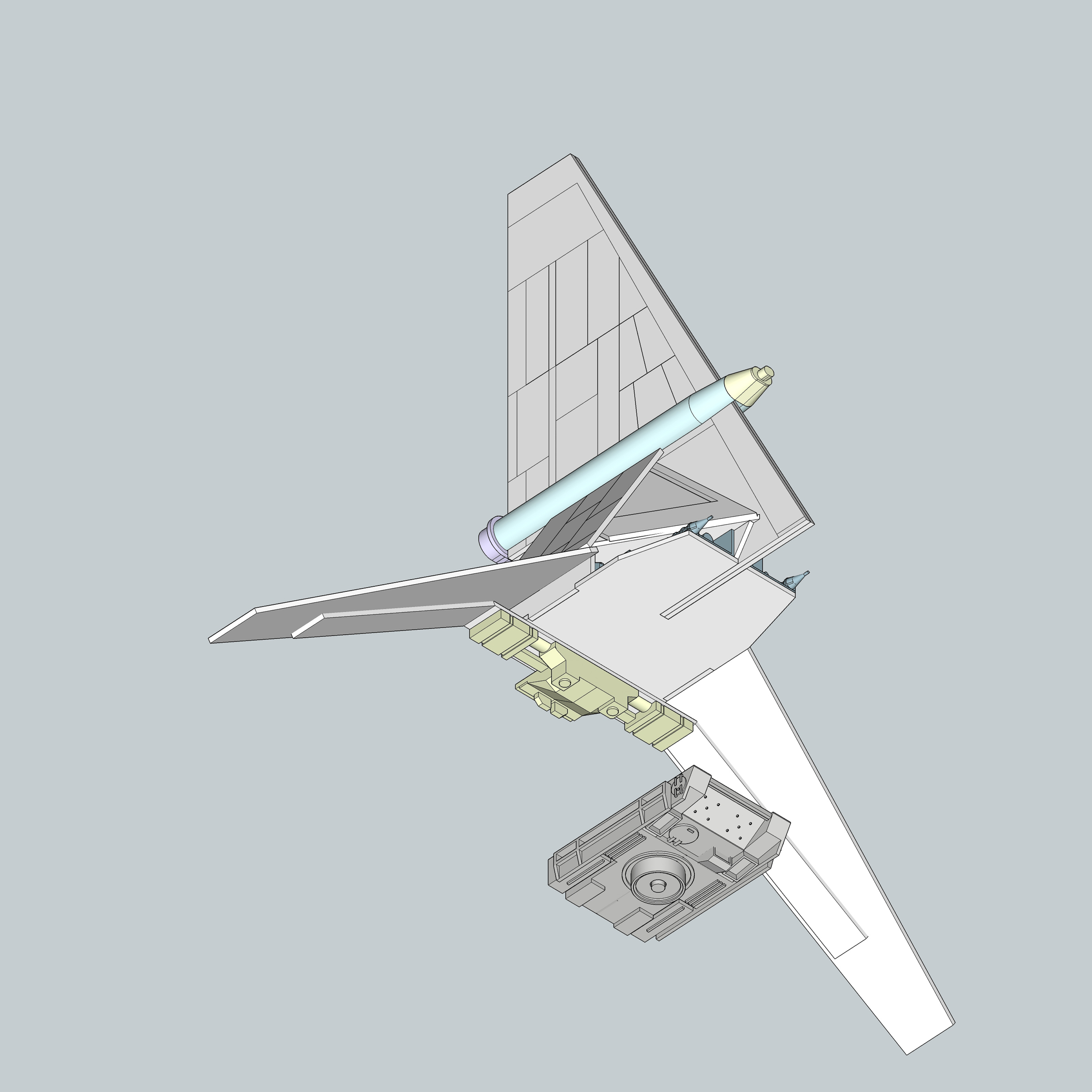
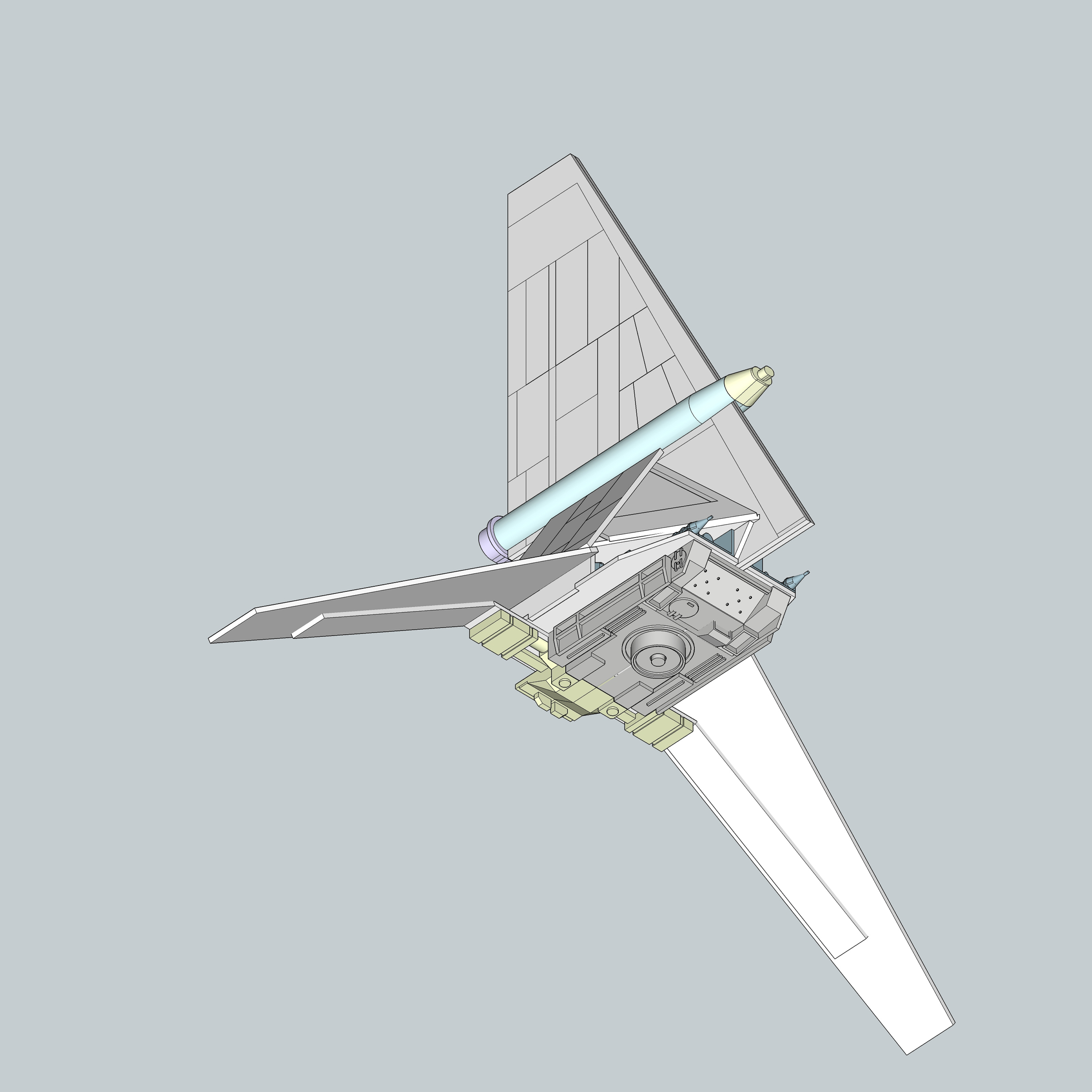
The undercarriage should be mounted flush against the rear piece and go right up to the lip of the styrene chassis.
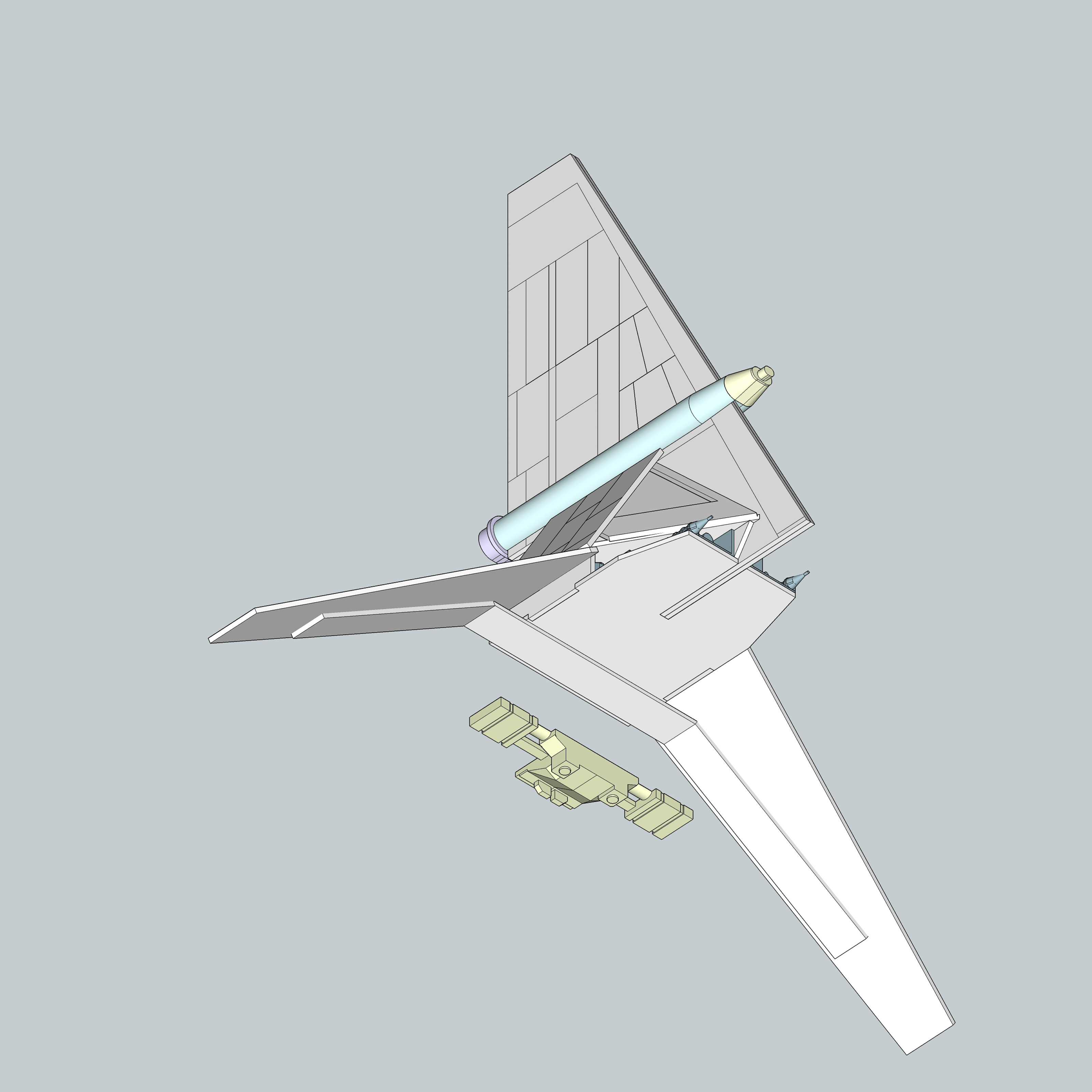
16 - Gun Base
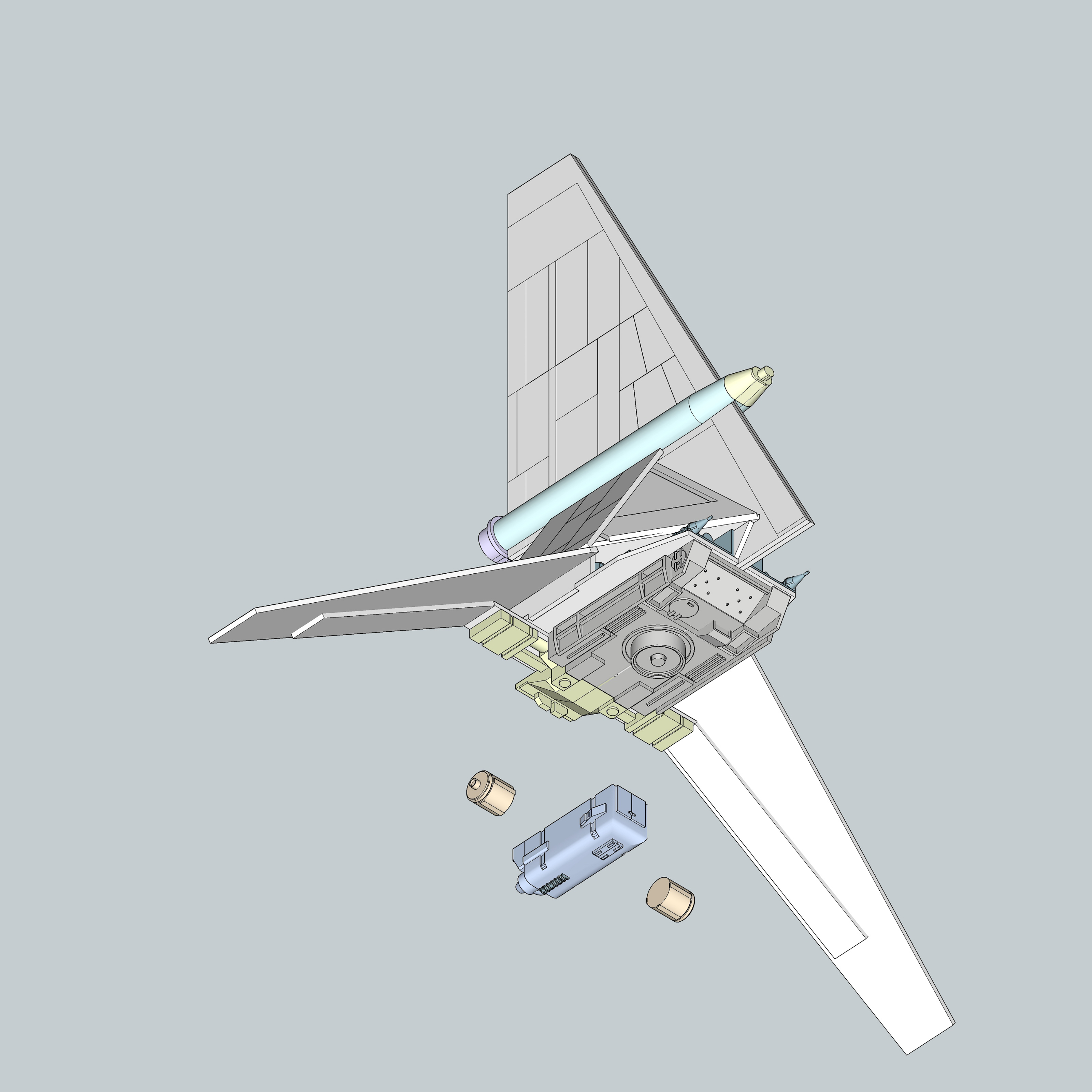


The two side barrels should be glued onto the sides of the gun base, which then slots into place on the chassis, where it fits right inbetween the raised areas of the undercarriage, which will keep it aligned.
It's not visible in these pictures, but the final version of this part includes a the hole for the .047" music wire which attaches the gun and serves as the main support rod pre-drilled.

17 - Gun and mounting rod
Is it just me, or does this seem like way more cannon than is necessary for bullseyeing two-meter womprats? I'm sure this could take out banthas and dewbacks easily (not that I'm advocating taking potshots at wildlife - Luke was clearly some kind of child psychopath).
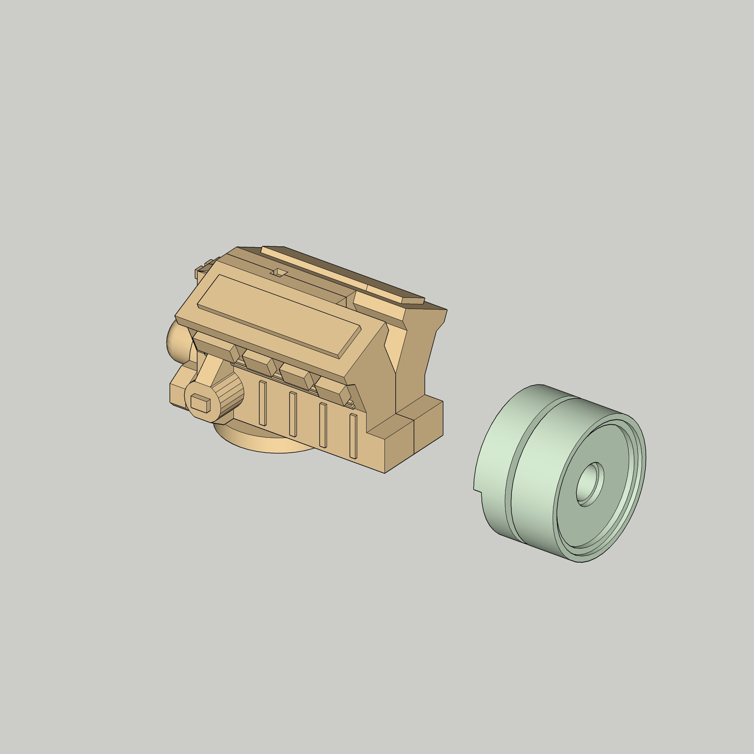


The V8 engine part which serves as the main body of the gun gets a piece added to the front - this piece should already have a 0.8mm hole in it to accept the .032" music wire barrel of the gun.
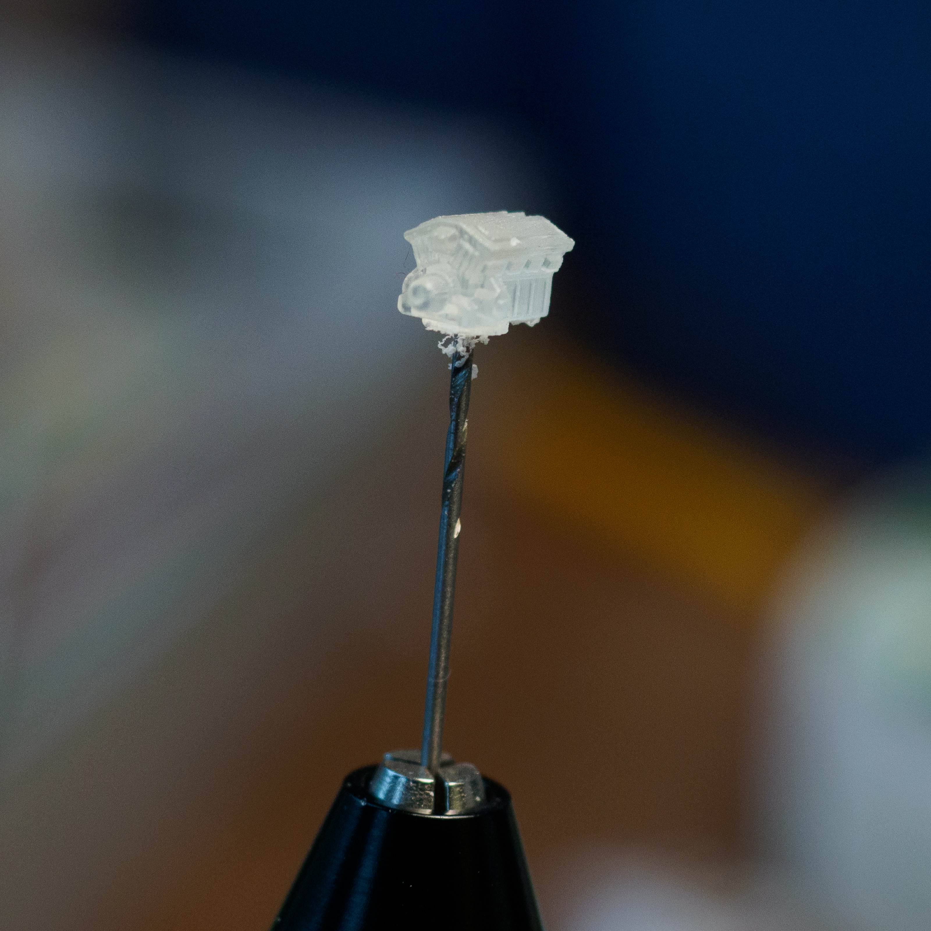

The V8 engine part then needs to have a 1.2mm hole drilled in it with a pin vise, to accept the .047" music wire rod. The circular part on the bottom has a divot indicating where to drill. Drill all the way through the top side, as the wire needs to go through the part entirely and into the base that's already attached to the frame.
Cut a 2.6mm long length of the 3/32" styrene tubing to act as a spacer inbetween the V8 part and the gun base. Make sure the V8 part is oriented correctly - the circle where you began drilling points downwards.


Cut a 35mm (1.4") long length of the .032" music wire to serve as the gun barrel shaft, and 13mm and 3mm sections of the 1/16" aluminum tubing to serve as the larger diameter parts of the barrel.
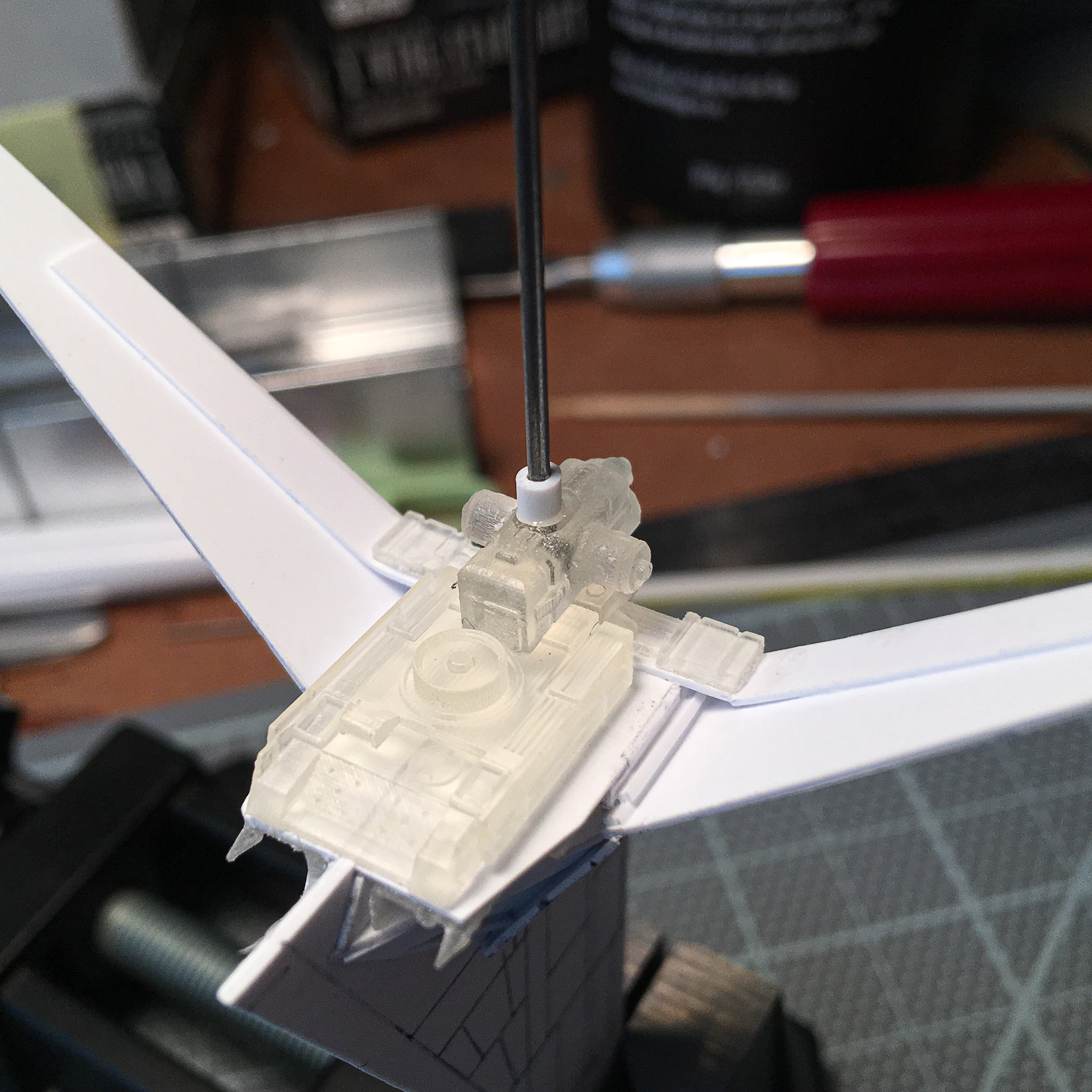
Insert the wire into the hole you drilled in the front of the V8 engine assembly and glue in place. Slip the aluminum tubing over the wire, position, and glue in place.
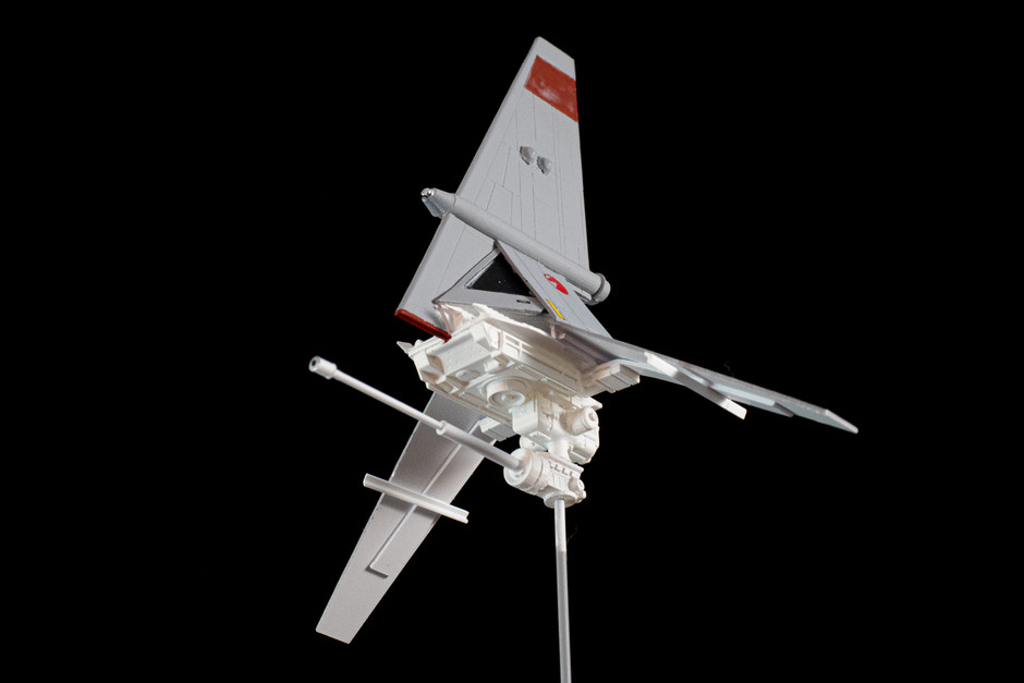
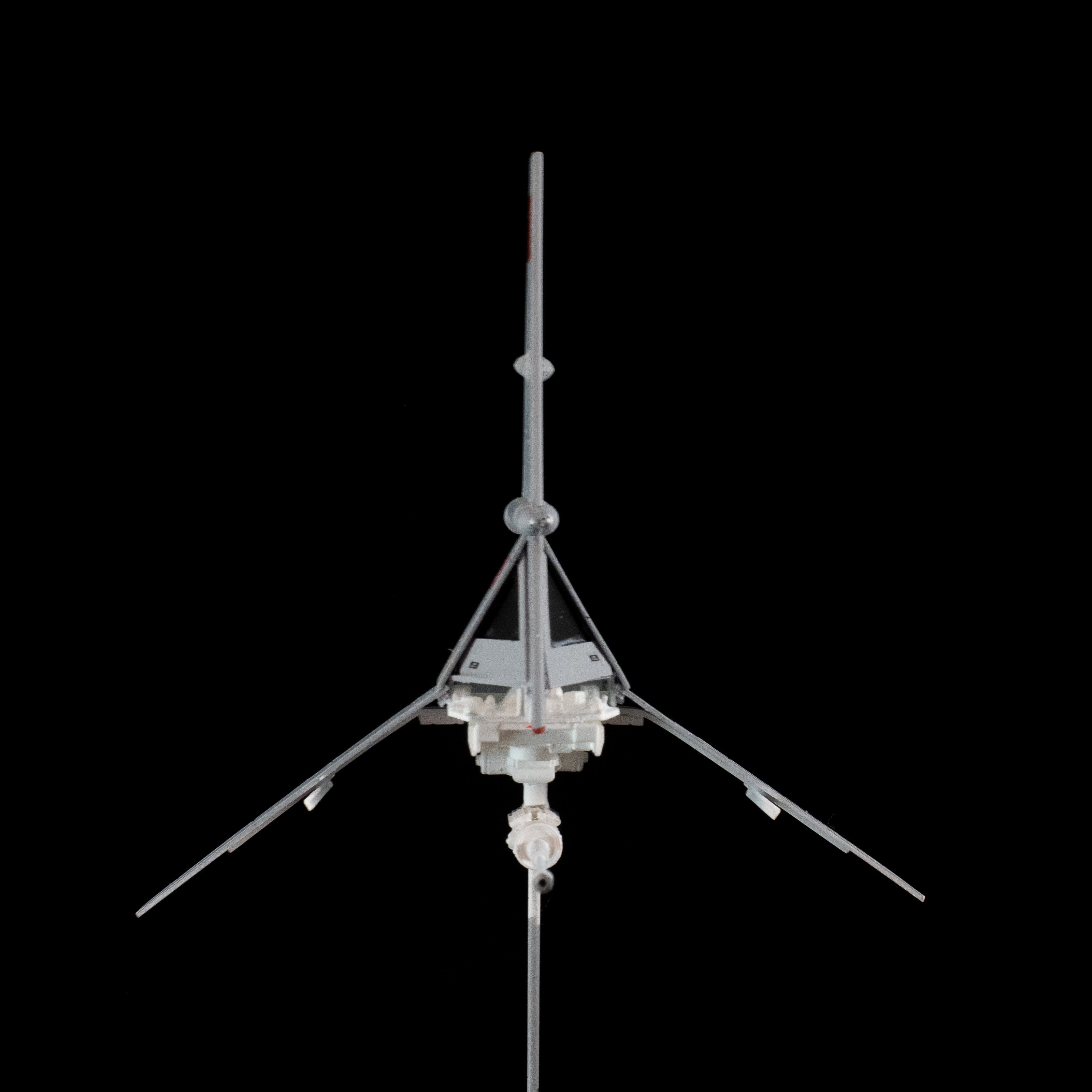
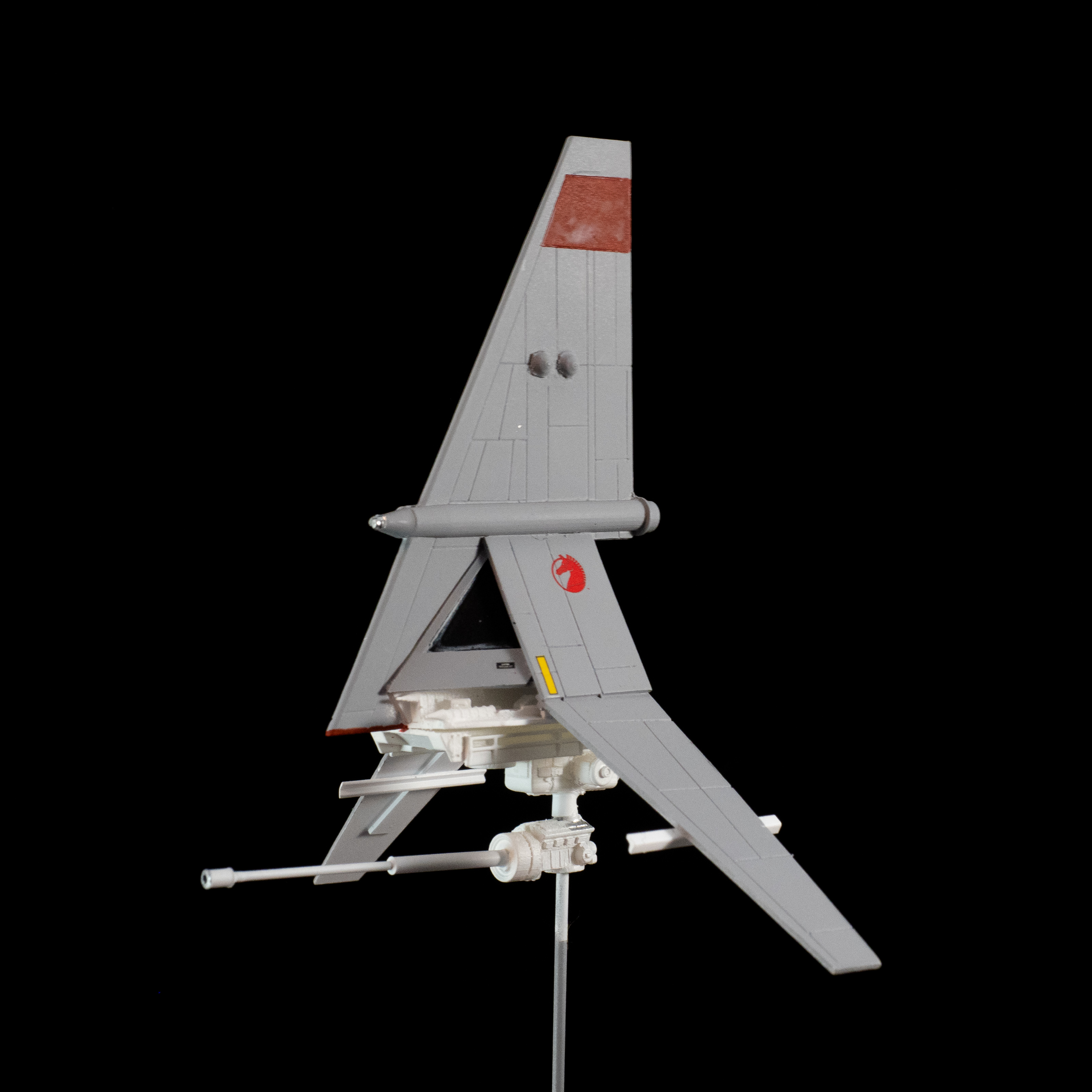
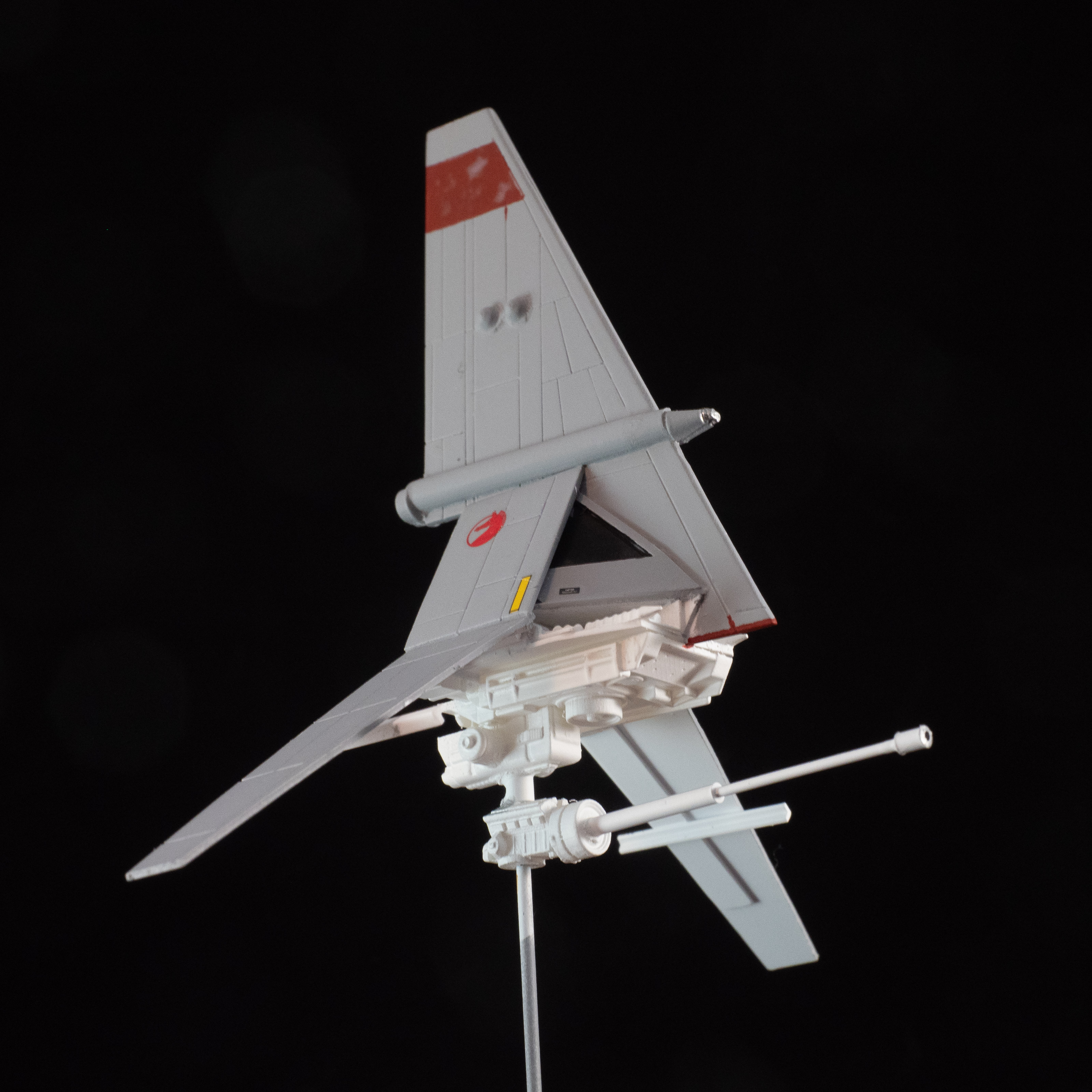
If at this point the whole thing looks about like this, congratulations, you're done!
